Metal shredders, formidable machines in the realm of industrial equipment, wield the power to transform large, bulky pieces of metal into smaller, manageable fragments. Within their robust exteriors lies a complex network of components meticulously designed to efficiently tear through various metallic materials. Let’s delve into the inner workings of these mechanical behemoths and uncover their structural intricacies.
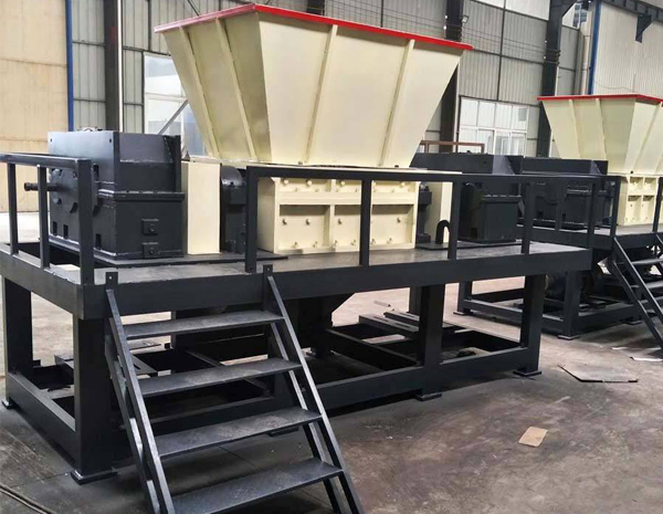
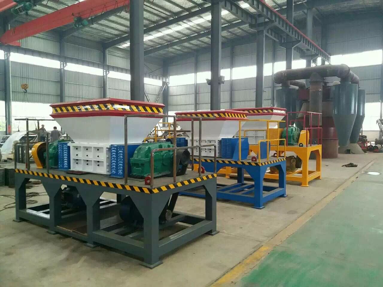
1. Frame and Housing: At the core of every metal shredder lies a sturdy frame constructed from heavy-duty materials such as steel or reinforced alloys. This frame provides structural integrity and support to withstand the immense forces generated during the shredding process. Encasing the machinery, the housing acts as a protective shell, safeguarding the internal components from external elements and ensuring operational safety.
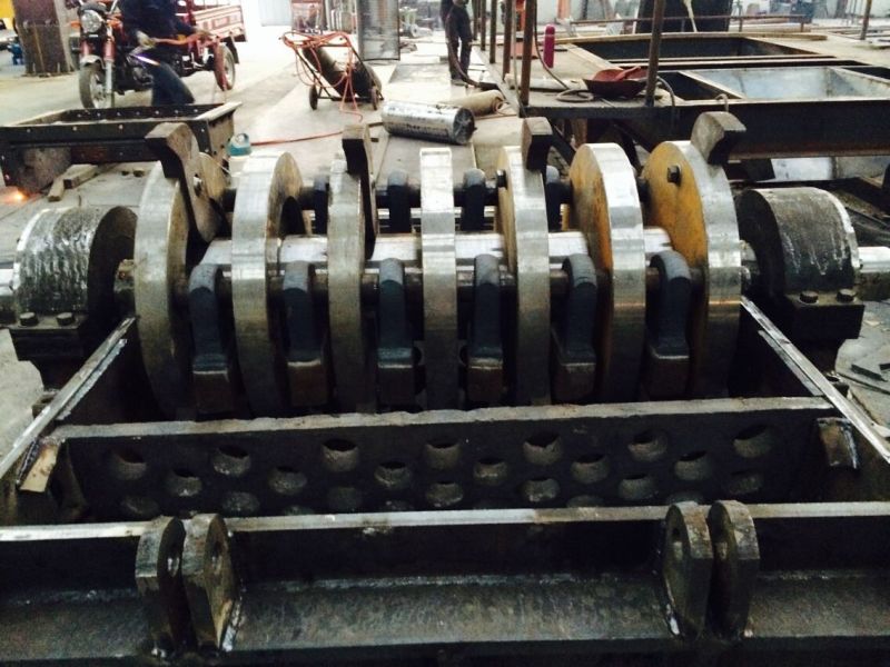
2. Rotor Assembly: Central to the shredding operation is the rotor assembly, a rotating shaft equipped with multiple blades or hammers. These blades, often made from high-strength steel or hardened alloys, are strategically positioned along the rotor to maximize cutting efficiency. As the rotor spins at high speeds, the blades forcefully impact and shear the incoming metal feedstock, initiating the shredding process.
3. Cutting Chamber: Within the housing, the cutting chamber serves as the arena where metal meets its demise. Configured to accommodate various sizes of metal scrap, the cutting chamber features a robust construction lined with wear-resistant materials to endure the abrasive nature of metal shredding. Adjustable screens or grates control the size of the shredded output, allowing for customization based on specific requirements.
4. Feed Mechanism: To facilitate a continuous shredding process, metal shredders employ a reliable feed mechanism responsible for introducing material into the cutting chamber. Depending on the design, this mechanism may utilize conveyors, hydraulic pushers, or gravity-fed systems to transport metal scrap into the path of the rotating blades. Proper alignment and synchronization are crucial to ensure consistent feeding and optimal shredder performance.
5. Drive System: Powering the shredder’s operation is a robust drive system comprising motors, gearboxes, and transmission components. Electric motors, often of industrial-grade, provide the necessary torque and rotational speed to drive the rotor assembly. Coupled with precision-engineered gearboxes, the drive system efficiently transfers power from the motor to the rotor, maintaining steady operation even under heavy loads.
6. Control and Safety Systems: Modern metal shredders incorporate advanced control and safety systems to monitor and regulate the shredding process. Programmable logic controllers (PLCs) or computerized control panels oversee various parameters such as rotor speed, feed rate, and system diagnostics. Safety features such as emergency stop buttons, interlocks, and overload protection mechanisms ensure operator safety and prevent equipment damage in case of malfunctions or anomalies.
7. Maintenance and Accessibility: To sustain optimal performance and prolong operational lifespan, metal shredders require regular maintenance and servicing. Access panels, hatches, and removable covers facilitate easy access to critical components for inspection, cleaning, and repair tasks. Scheduled maintenance routines, including blade sharpening or replacement, lubrication of moving parts, and inspection of wear surfaces, are essential to prevent downtime and maintain productivity.
In conclusion, the internal structure of a metal shredder embodies a synergy of robust engineering, precision machining, and advanced technology. From the formidable rotor assembly to the intricate control systems, each component plays a vital role in the relentless pursuit of metal shredding efficiency and productivity. As these machines continue to evolve, driven by innovation and engineering ingenuity, they remain indispensable assets in the realm of metal recycling and industrial processing.